Over the last few years I developed an interest in the relationship between audio and video, basing both my project and thesis in year 3 and 4 of my music degree on the subject. Ive made several Max for Live jitter devices for Ableton and created some basic music videos using some of them on my YouTube page. One video in particular got some messages on how I created the video , so I decided to make it my next tutorial , my third Max for Live jitter one on this site.
Ive written a tutorial on creating a basic Max for Live device here, but for the purpose of this guide I will go through the basics again.
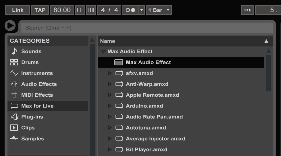
To create a Max for Live device we first open up Ableton Live. Select Max for Live and drag in an empty Max for Live audio effect into the master channel.
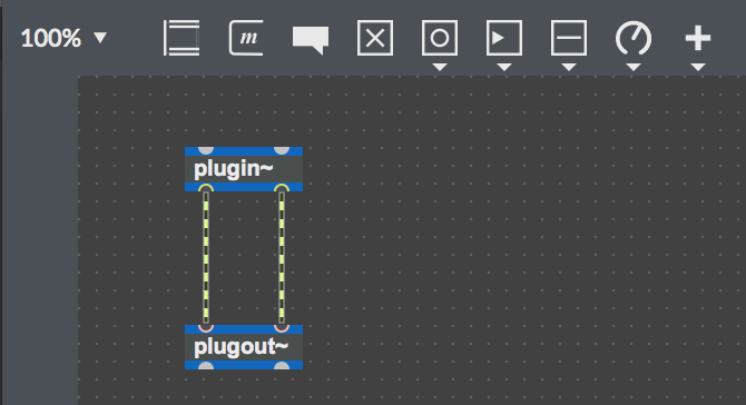
This creates an empty audio device patch with just the plugin~ and plugout~ objects. These represent the audio coming from Ableton Live and the audio being sent to the audio output device.
When creating an audio effect, signal (which is indicated by the green and white patch chords) from Ableton is routed through a created effect and then sent to the left and right outputs.
For a Jitter patch, a copy of the audio signal is taken for audio analysis while leaving the plugin~ and plugout~ objects intact. This means that the audio will play as normal while also being sent to the relevant Jitter object for audio analysis. Removing the left patch chord will interrupt the audio signal and prevent audio coming out on the left stereo channel and removing the right patch chord does the same with the right audio channel.
Drag in a track of your choice to an audio channel, this will be used for audio analysis for the creation of the jitter patch. When developing patches and for trying them , I usually pick a track which has clear transients , for example one which might start of melodic and have a clear bass-line and steady drum beat, this allows us to see how the video reacts to sound and if it needs to be adjusted in any way.
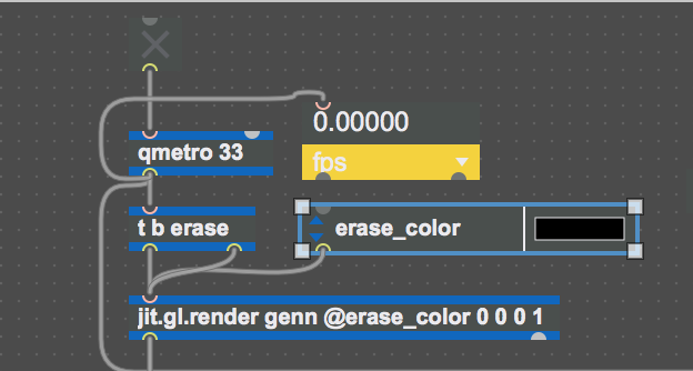
The Qmetro object bangs out frames per second, this is activated using the toggle and once it is selected the Qmetro starts the video. The Qmetro object has low priority properties, compared with the Metro object which triggers a bang at the set interval at all times. Meaning it will slow down in triggering bangs depending on current CPU usage, resulting in a lower frame rate. To view the frame rate , the jit.fpsgui object is used, this should ideally stay above 30 frames per second, if it drops to below 20 then something the patch is causing extra CPU usage . This is attached to the jit.gl.render object.
To allow of the drawing and rendering of OpenGL, the jit.gl.render object is needed. This renders OpenGL objects to the destination window.
For a video to be rendered successfully , a message is required to allow for the erasing and drawing of frames. A trigger bang erase message is used , this first erases the existing frame , then receives a bang from Qmetro releasing a new frame and the trigger to draw the next frame, this process is then repeated. By leaving out this message will result in the image being constantly drawn over and over again on the same frame.
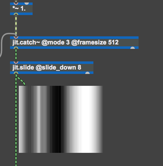
To analyse the audio , the jit.catch~ object is used which transforms audio into matrices. These matrices can be seen by connecting the jit.pwindow to the outlet of the object.This object should not be left in your patch as it uses an amount of CPU, I use the jit.pwindow object to test the signal flow in case the patch is not working correctly.
Jitter is integrated with the Max software in that objects relevant to Jitter (which begin with jit.) are connected to each other for real time processing and in the development of creating your own unique video effects, real time video mixers and audio visualisers.
Jitter is designed for the efficient manipulation of large batches of data. The general container for this data is jit.matrix. This object requires arguments to set the name of the matrix, the number of planes per cell, the type of data to store and the size or dimensions of the matrix. By naming the matrix , other objects can be told how to find its contents. By referring to the name of a matrix , objects can share data and have access to its contents. Each cell in a matrix has a specific address , for a two dimensional matrix , the first cell would have an address of 0,0.
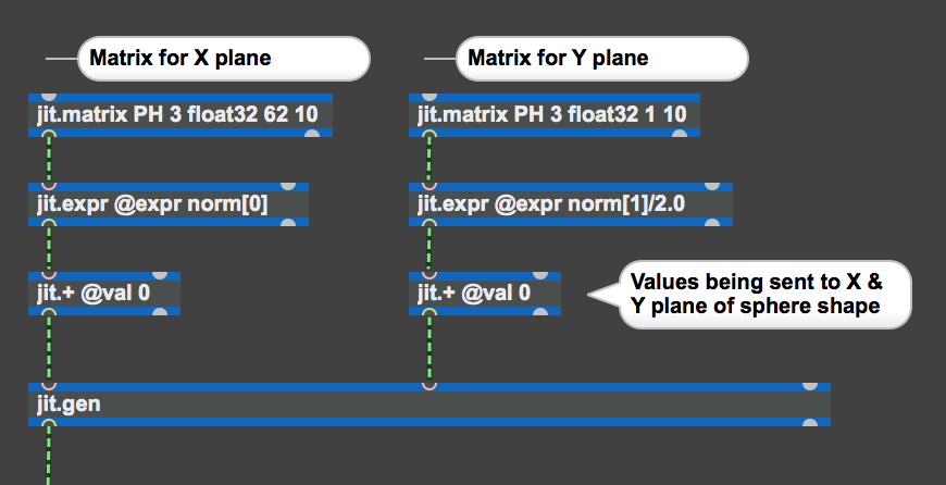
Jitter objects communicate to each other through the matrix, for example a receiving Jitter object would get data from a specified place in the matrix, modify it in some way and then send out the name of the modified data to all connected Jitter objects. In Max , the jit.matrix object is used to create a storage spaced for a named matrix of data. PH is the unique name given to the matrix , this allows for the reference to the matrix so other objects can share data and have access to its contents.
The number 3 refers to the amount of planes per cell (X,Y and Z in this case of this patch), Jitter stores an additional piece of information called the alpha plane. This stores information on how transparent a pixel should be when overlaid on an image , it is used for masking and mixing effects notably transparency and opacity. Float32 refers to the type of data being used in the matrix, by specifying the data type makes the processing of data more efficient, the different data types supported in Jitter are Char (8 bit), Long (32 bit), Float 32 (32 bit floating point number) and Float 64 (64 bit floating point number). The final to numbers “62 10” refer to what will be drawn in this patch , which is 62 points around the circle and 10 circles.

A Matrix is created for the X and Y plane as seen below, the audio analysis data is sent to the jit.+ objects to animate aspects of the sphere, X plane is the amount of circles and the Y plane is the angle, in the more advanced patch I created (available upon request), beat detection is sent to the X plane causing the sphere to move every time a kick drum sounds , this is one of the advantages of using Gen .
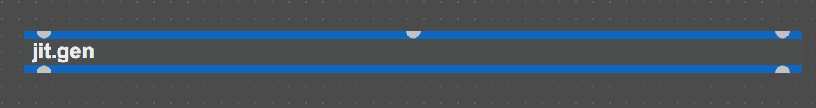
To create these circles we use the jit.gen object , this generates shapes from a patcher using code/math expressions. The advantage of using this object in terms of Jitter and OpenGL is the ability to create shaders and non generic shapes. The link here explains more about Gen if you want to read up on it more.
While the patch is locked(CMD+E), double click on the jit.gen object to open it , a window will pop up as seen in Figure 9 & 10.
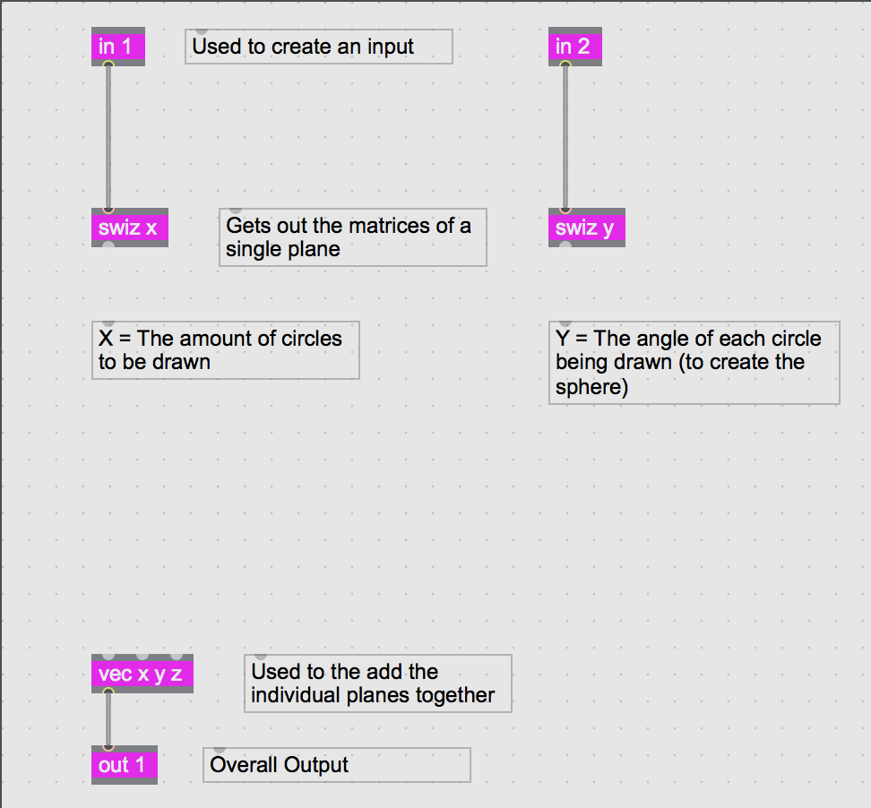
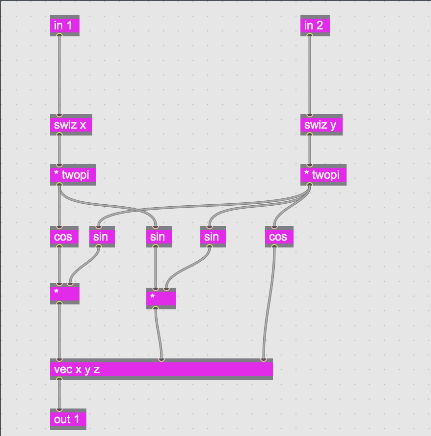
Without getting into the maths too much , Im going to explain what is happening inside this Gen sub patch as seen in Figure 10.
The in 1,2 and 3 creates three inputs on the jit.gen object , these are represented by the three grey semi-circles seen on the top of the object in Figure 8. Input 1 is the X plane , Input 2 is the Y plane and Input 3 is the Z plane , this allows audio analysis to be sent to different parts of the shape , for example you could have the bass going to the X plane , the Mid to the Y plane and the Treble to the Z plane , one way of doing this would be to use the Peakamp object which would help trigger a bang each time a kick drum is sounded, causing some animation to the shape , I have this implemented in a different version of this patch and can email it to anyone who wants it.
Swiz gets the matrices of a single plane from our three plane matrix and Vec x y z is used to add them together again.
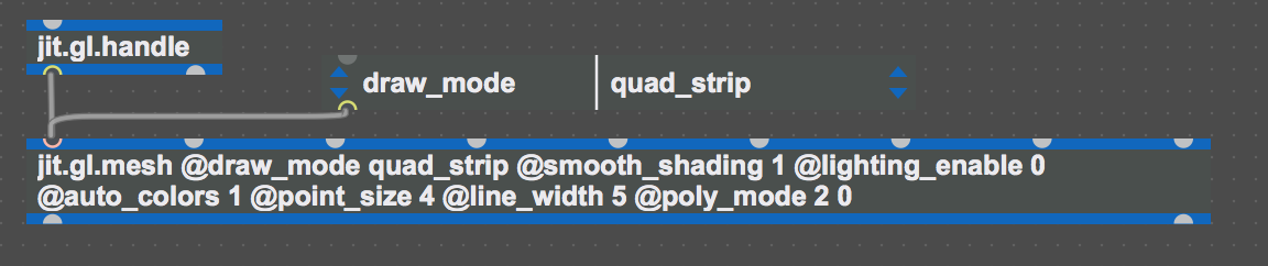
The Out is then attached to the jit.gl.mesh object, through changing attributes give you the ability to have different draw modes such as polygon, line, point, triangle, quads and line loop. These determine how the shape will be drawn. The @auto_colors attribute is added to give an array of colour onto the gen created shape.
The jit.gl.handle object is added, this allows you to move the gridshape with your mouse, it can be rotated, zoomed in and out (hold alt and click mouse), or positioned on screen (hold Cmd and click mouse)
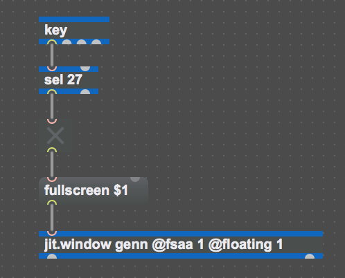
To allow the function to switch between full screen, the key and sel objects are used. By using ascii where each key on the keyboard is given a number, any key can be used to trigger a message in Max MSP. In the case of this patch, the escape key is set to switch between full screen, being ascii number 27, once this key is pressed, it turns the toggle one which activates the full screen message which is being sent to the jit.window object
Below is a screenshot of the full patch with labels , as you can see , theres not much needed to create an audio reactive device for Ableton Live. I have this version and a more advanced version with effects and beat detection added complete
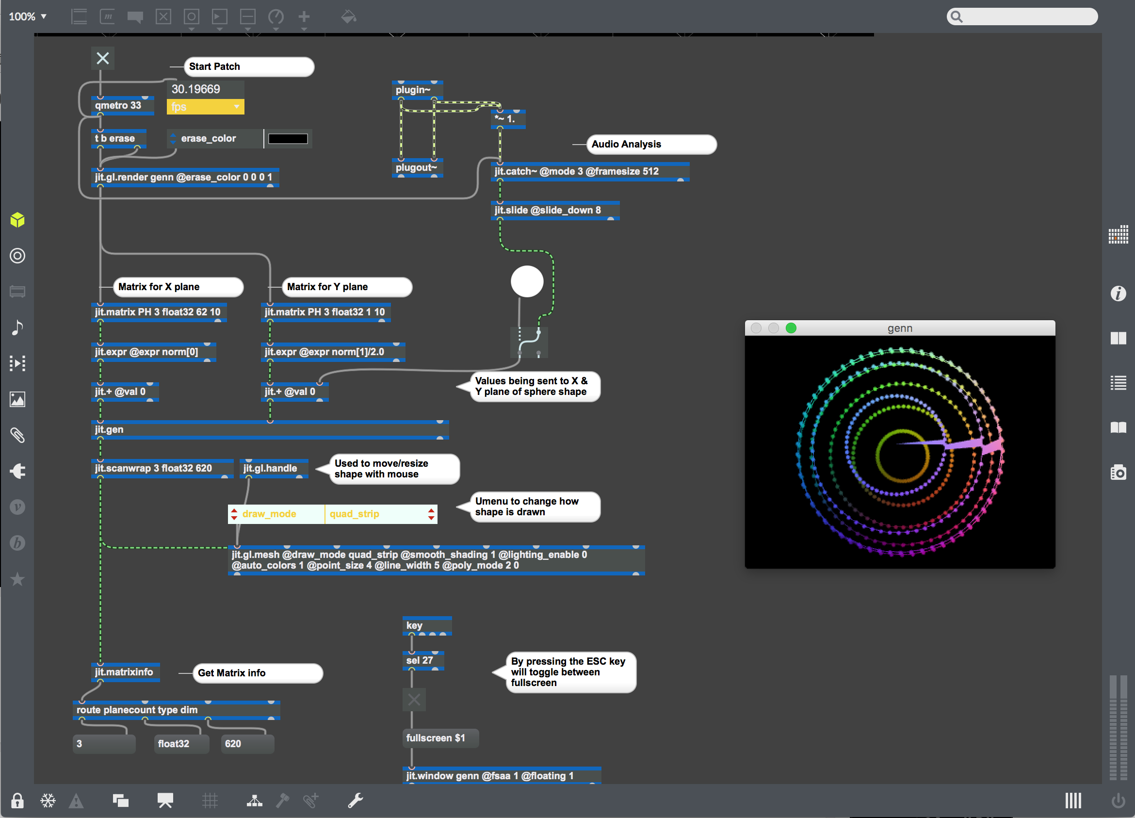
If you have any questions or would like a copy of the patch, feel free to leave a comment ,thank you for reading.


very cool tutorial, where can i download the patch ?
LikeLiked by 1 person
Hi Phil , I just quickly recreated the patch for you as and it is available at the link below , let me know if the link/patch works alright .
(https://www.dropbox.com/s/mkkg5f8v3pqhtnt/visual%20device%20blog.amxd?dl=0)
LikeLike
Thank you very much. It’s definitely working. This is a great starter device for beginners with jit. I’m gonna explore it.
LikeLiked by 1 person